Protective Devices
Protective devices for electrical circuits ensure that a high current cannot flow under faulty conditions, protecting the installation and equipment and preventing injury and harm to persons handling or in the near vicinity of equipment. Overcurrent protection is assured through physically detaching the power supply in a circuit, which removes fire hazards and risk of electrocution.
Protective devices might include:
- Fuses.
- Miniature Circuit Breakers (MCBs).
- Residual Current Devices (RCDs).
- Residual Current Breakers with Overcurrent (RCBOs).
All of the aforementioned devices protect users and equipment from faulty conditions in an electrical circuit by isolating the electrical supply. Fuses and MCBs only isolate the live feed; while RCDs and RCBOs isolate both the live and neutral feeds. It is essential that the appropriate circuit protection is installed to ensure an electrical installation is safe.
Fuses
A fuse is a very basic protection device used to protect the circuit from overcurrent. It consists of a metal strip that liquefies when the flow of current through it surpasses a pre-defined limit. Fuses are essential electrical devices, and there are different types of fuses available based on specific voltage and current ratings, application, response time, and breaking capacity.
The characteristics of fuses like time and current are selected to give sufficient protection without unnecessary disruption.

Miniature Circuit Breaker (MCB)
An MCB is a modern alternative to fuses, and are usually centrally located in buildings – usually called a “fuse box” or “breaker box”, or attached to specific equipment. They are just like switches, turning off when an overload is detected in the circuit. The basic function of a circuit breaker is to stop the flow of current once a fault has occurred. The advantage of MCBs over fuses is that if they trip, they can be reset without having to replace the whole MCB. MCBs can also be calibrated more precisely than fuses, tripping at exact loads. Circuit breakers are available in different sizes from small devices to large switch gears which are used to protect low current circuits as well as high voltage circuits.

Residual Current Device (RCD)
Residual Current Devices (or RCDs) are designed to detect and disconnect supply in the event of a small current imbalance between the live and neutral wires at a pre-defined value - typically 30mA. RCDs can detect when a live conductor touches an earthed equipment case, or when a live conductor is cut through; this type of fault is potentially dangerous and can result in electric shocks and fires.
An RCD does not give safety against a short circuit or overload in the circuit. It cannot detect – for example - a human being accidentally touching both conductors at the same time. An RCD cannot replace a fuse in function.
RCDs can be wired to protect a single or multiple circuits - the advantage of protecting individual circuits is that if one circuit trips, it will not shut down the whole building or distribution system, just the protected circuit.

Residual Current Breaker with Overcurrent (RCBO)
An RCBO combines the functions of a MCB and an RCD in one unit. CRBOs are a safety device which detects a problem in the power supply and is capable of shutting off in 10-15 milliseconds.
They are used to protect a particular circuit, instead of having a single RCD for the whole building.
These devices are testable as well as are able to be reset. A test button securely forms a tiny leakage condition; along with a reset button again connects the conductors after an error state has been cleared.

Grounding/Earthing
Uncontrolled electricity can injure or even kill humans or animals. A common and effective way to control electricity is through grounding. Grounding is a physical connection to the earth that draws electric charge safely to the ground allowing a large space for electrons to dissipate away from humans or equipment. A grounding system gives excess positive charge in electrical lines access to a negatively charged ground wires, eliminating the dangers of fire and electrocution.
Some devices may have a "ground" symbol indicating where a grounding wire should be connected.
The term "ground" refers to a conductive body, usually the earth. "Grounding" a tool or electrical system means intentionally creating a low-resistance path to the earth’s surface. When properly done, current from a circuit follows this path preventing the build-up of voltage that would otherwise result in electrical shock, injury and even death. Grounding is used to dissipate the damaging effects of an electrical short, but also used to prevent damage from lightening as well.
There are two ways to ground devices:
- System or Service Ground: In this type of ground, a wire called "the neutral conductor" is grounded at the transformer, and again at the service entrance to the building. This is primarily designed to protect machines, tools, and insulation against damage.
- Equipment Ground: This is intended to offer enhanced protection to the people. If a malfunction causes the metal frame of a tool to become energised, the equipment ground provides another path for the current to flow through the tool to the ground.
A major aspect to grounding to be aware of: a break in the grounding system may occur without the user's knowledge. Using a ground-fault circuit interrupter (GFCI) is one way of overcoming grounding deficiencies.
In tandem with a residual current device (RCD), grounding is essential to interrupting the power supply if there is an insulation fault—for example, if a live wire comes loose and touches the metal surface outside a piece of equipment. A ground wire channels the fault current into the earth, preventing injury to people. The earth connection picks up fault currents, allowing RCDs to measure them and trip.
When grounding circuit components and appliances, the cabling should have an electrical resistance below the maximum threshold of the main service breaker:
- 100Ω for a 500mA RCD
- 167Ω for a 300mA RCD
- 500Ω for a 100mA RCD
The lower the resistance, the better a grounding system will work.
Grounding System Components
The connection between metal parts and grounding is made using a third wire in the electrical circuit. Ground wires usually have a green-yellow colour and must have the same gauge as the biggest wire used on the installation to protect.
To check if a grounding connection has been installed, look for the following points:
- Plugs and sockets have a grounding pin.
- Plugs with grounding pin are connected to a 3-wire network.
- Ground wires are well connected to each other on the distribution board, normally through a grounding pad or a connecting strip in metal.
- The grounding pad or the connecting strip is connected to the ground and this link must be done with a high-thickness wire (for example, 16mm²).
- This wire is connected to the ground.
| Ground Connecting Cables in Use: | |
|---|---|

| 
|
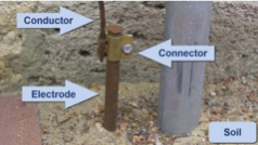
A grounding system typically consists of a grounding conductor, a bonding connector, its grounding electrode (typically a rod or grid system), and the soil in contact with the electrode. An electrode can be thought of as being surrounded by concentric rings of earth or soil, all the same thickness - each successive ring having a larger cross-sectional value and offers less and less resistance until a point is reach that it adds negligible resistance.
