Another widely used radio band used by humanitarian actors is the High Frequency (HF) range. HF is used less frequently by commercial or governmental organisations, but due to the extremely long range communication provided by HF, it has become popular for use in aviation and remote exploration.
HF radio waves occupy the band between 3 and 30 megahertz (MHz), and are part of what is known as the shortwave band. HF transmit using “skywave” or “skip” propagation, giving HF the ability to send and receive over long distances. HF radio waves occupy a spectrum that interacts with the earth’s atmosphere in a very specific way – when broadcast at an angle towards the they will refract off the ionosphere and back towards the earth’s surface where it will bounce back multiple times. HF radio wave are capable of broadcasting signals beyond the horizon and around the curvature of the earth’s surface. In optimal conditions and using the appropriate set up, HF waves can even be transmitted between continents, however this should never be relied on as a primary mode of intercontinental communication. HF radio waves refracting off the ionosphere greatly reduce dead spots and radio “shadows” cast by hills our mountains, however dense surrounding buildings may still effect HF usage.

While HF may offer an advantage in the distance of its communication, it also comes with limitations. Notably, the equipment required to transmit and receive HF signals is bulky and large, and requires a significantly larger antenna and a larger energy source. Generally speaking, there are no good solutions for handheld mobile HF radios used by humanitarian agencies – HF is almost always limited to vehicles and stationary buildings.
Vehicle HF Radios
HF communication has become the default for vehicle communication for many large humanitarian agencies. Due to the fact HF signals can reach far beyond VHF/UHF, and given the size of the equipment, HF is an excellent compliment to other forms of communication and a vital for vehicle security.
The vehicle mounted HF transceivers are very similar to other vehicle mounted radio units – HF radios are installed on, in or below dashboards, and must be permanently wired to the vehicle’s battery or electrical system. Additionally, given the placement of the HF antenna, additional wires will have to be run through the chassis or body of the vehicle to properly reach the transceiver.
A distinguishing factor of an HF antenna is its sheer size. The length of an HF antenna installed in a car – sometimes called a “whip” - may be several times the height of the vehicle. Also, while the antenna may not be especially heavy, it’s length will apply pressure to the base of the antenna as it encounter breeze or as the vehicle starts and stops. The HF whip will need to be securely bolted to the body of the vehicle, usually on the front or rear bumper.
| Example HF (Codan) Vehicle Antennas | |
|---|---|
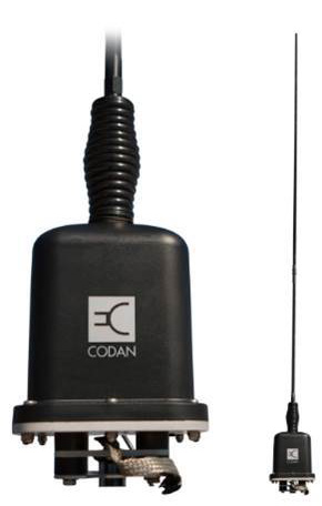
| 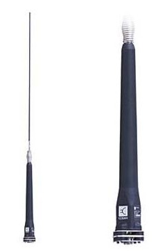
|
The antenna itself may cause security concerns. While the radio is in use, there is a significant amount of electricity flowing to the antenna if only for a short period of times. Persons or animals in contact with the antenna while in use may suffer heat or electrical injuries. Additionally, the height of the whip can easily become caught on trees, bridges, or any low hanging materials or structures, damaging the structure, the whip or both.
To remedy the height issues, users may want to tie back or anchor their HF antenna to a roof rack or other anchor point on the roof of the vehicle. While this is a perfectly acceptable solution and does not impact the functionality of the radio, users should be aware:
- Anchored whips are under high tension, and may injure people or animals if it breaks free.
- Whips can only be anchored using special built tie downs, available from the manufacturer.
- The whip should never be closer than one meter to the body of the car.
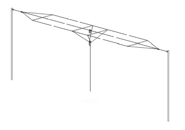
| HF Vehicle Antenna Configurations | |
|---|---|
 |  |
HF Base Stations
The size and usage of an HF base station isn’t dissimilar to other radio base stations, however specific usage requirements will depend on the specific unit and the programming needs of the agency.
A significant difference with using permanent HF building installations however is the size and orientation of the HF antennas. Due to the relative size of the HF radio wave, HF base antennas need to be extremely large. To accommodate this, HF antennas tend to be made of flexible materials that can shaped to match the contours or needs of the grounds. The most common HF antennas come as di-polar – two separate conductive cables interrupted in the middle. the two separate cables are loose hanging, but separated by rigid bodies that prevent the two from making contact with each other.
| Di-Polar HF Antenna |
|---|

|
The HF di-polar antenna can take up quite a bit of space in a compound area. The antenna can be up to 40-50 meters longs insulator to insulator, and actually be longer accounting for the tie downs and the anchors. HF Antennas also must be mounted fairly high above the ground. The general rule of thumb is radio antennas should be mounted at least half the height of their corresponding wavelengths. For HF radio installations, it is recommended to install the antennas at least 12-15 meters above the ground.
Considering the ground space required to accommodate this, there are several configurations that users can adopt:
| Horizontal Configuration | Inverted V Configuration |
|---|---|
| 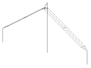
|
Horizontal Configuration – The di-polar antenna is tautly suspended from both ends at equal heights. The cable connection to the base station is free hanging, though ideally it will still be secured to something near the ground level or anchored to a sturdy pole to prevent movement in the wind, and to take weight off the installation. The horizontal configuration is considered the best case, and will carry a signal the furthers.
Inverted V Configuration – To save ground space, agencies may opt for the inverted V configuration, where the sides of the di-polar antenna are sloped like a tent. Important components to an inverted V configuration:
- The angle formed by the inside of the V should never be less than 90 degrees. The closer to flat the better.
- The middle will need to be suspended from a strong, non-conductive material using the proper anchor.
- The anchors at the low points of the slope should still be raised above the ground, connected to “stub masts”. Ideally, the main mast would be raised higher than the minimum height to accommodate the height of the lower points.
Any form of antenna and mast configuration will need to be safely secured. Each antenna type comes with a certain wind rating, and users should understand what annual weather might impact antenna selection.
Additionally, HF antennas can consume and output large amounts of electricity. HF di-pole antennas while in use consume 250-350 watts of power on average, and can have peak consumption of up to 1,000 watts. Di-polar antennas are largely just exposed metal, and any thing bridging the connection between those two wires will pose a serious risk. Tree branches or trash might catch fire, while wires can seriously injure or kill humans or animals. At no point should humans or animals be able to grasp or bump into the wires of an HF radio, and if a radio wire is knocked down, persons in the vicinity should be instructed to stand back until the power is cut.
